Side by side comparison of choral recording techniques – XY vs AB

Recording a choir and organ in a church is one of the hardest things a recording engineer can do. There are loads of guides on the internet that explain how to use which type of microphone to use and where to put it, but most of these guides fail to give clear advice on recording in a church. It’s not the fault of the guides; the sound in a church depends on the size and layout of the church, where the choir are and where the organ is just as much (if not more) than the quality of the sound itself. There are just too many variables to be able to give concrete recommendations.

I’ve been recording the choir at St Mary’s, Fishponds for several years now and I’ve been making incremental improvements all the time. From the beginning, I owned a pair of small-diaphragm condenser (SDC) microphones with cardioid pickup patternBehringer C-2.

At the beginning I used these cardioid SDCs in the tried-and-tested XY pattern – also known as coincident pair. You mount the microphones pointing inwards at 90° to each other, with the tips touching. The results were OK. The consonants were sharp but there was not much reverb and the organ (which is at the far end of the building) didn’t sound great.

X-Y microphone placement

Later I experimented with these cardioid microphones arranged in an ORTF pattern – also known as near-coincident. The microphones are mounted pointing away from each other at about 100° and with the tips about 17cm apart. I wrote about ORTF at the time and I preferred the results to XY.

ORTF microphone placement

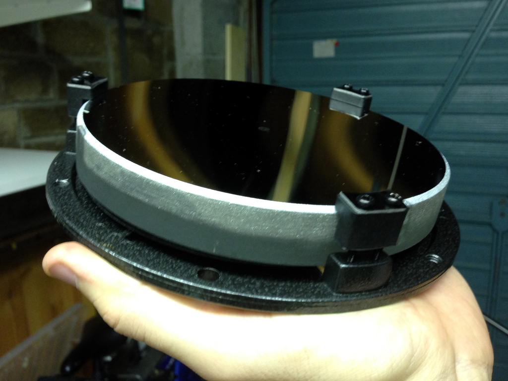
More recently, I got my hands on a pair of SDC microphones with omnidirectional pickup patternBehringer B-5. The norm for stereo recording with omnidirectional microphones is to use the microphones facing the same direction but spaced a few feet apart – a so-called “spaced pair” or an AB pattern. The spacing depends on the building and the “size” of the sound source (solo artist vs choir).

AB microphone placement

As with any new microphone, it can’t be trusted until it has been tested – so I recorded a service this week using the XY and AB methods simultaneously. This picture shows the setup. The microphone stand in the middle is holding the pair of XY cardioid microphones while the two stands flanking it, near the pillars, are holding the spaced pair of AB omnidirectional microphones.

AB and XY microphone placement

To give you some context of the size and shape of the church, here’s a drawing I made. All dimensions are in metres. The two grey blocks near the top of the drawing are the choir stalls. The rectangle with diagonal corners cut off is the step that’s visible in the photo above, and that’s where I put the microphones. To make matters more complicated, the organ pipes are above the door at the very back of the church (bottom of the drawing).

St Mary's Church
St Mary’s Church

I much prefer the AB placement and so do a couple of people who have heard the recording. But it’s up to you to decide! I’ve included two clips: the first is a short section of Sanders‘ responses, to illustrate the sound of an unaccompanied choir. The other is the tail end of the Gloria from Stanford’s Evening Service in C, to illustrate the sound of the organ.

Sanders responses – AB


Sanders responses – XY

Stanford in C – AB


Stanford in C – XY

Personally, I find that the AB recordings sound smoother and mellower, provide a better stereo image, a more realistic balance between choir and organ, and a nice ambience of the room. Of course that’s just my opinion based on one test recording, so your mileage may vary. This Sunday it’s Advent Carols at St Mary’s and I will be recording again. I plan to use only the AB microphone placement and I think I will place the microphones slightly closer together.

I hope these notes will be of use to someone who is thinking of recording in a church 🙂

Pinched optics – the cure

If you’ve been following my geeky astronomical posts lately, you’ll see that my new telescope suffers from triangular stars, caused by pinched optics. I’ve also been posting about the problem on Astronomy Forum. Just to recap, the telescope currently produces pictures like this. The effect is subtle, but if you click on the picture to see the larger version, you can clearly see the triangular stars.

M45 Pleiades cluster

For those who are unfamiliar (although there’s no excuse not to be familiar with the inner workings of telescopes if you follow my blog! :P), reflecting telescopes have a thick glass mirror. The mirror is held in a circular structure called a mirror cell, which is basically a disc of metal with three (or more) clips that hold the mirror in place. Here’s my mirror in its cell.

Mirror and cell
Mirror and cell

Now here’s the rub (literally). Although the mirror is thick glass (almost an inch) and very heavy, it is actually quite flexible. It doesn’t take much pressure on the mirror to warp it, which is what’s causing my triangular stars. The three clips on the front of the mirror were pressing down quite firmly, and warping it. The top part of the clips is rubber, but it was still enough pressure.

However, that’s not all. After I loosened the three clips by undoing the screws a bit, I noticed that the mirror was actually wedged tightly in between the metal pegs at the base of each clip. It shouldn’t be touching those at all.

Primary mirror clip
Primary mirror clip

Not only was my mirror touching the sides of the clips, it was wedged tightly down. It wouldn’t budge, and must have required significant effort to wedge it in there. I contacted the retailer, Teleskop Express, to ask what they recommended. This is their reply:

you are probably right – it is the sideways pressure of the mirror clips. This can be more pronounced if the temperatures get lower. The best way to deal with this problem is to take the mirror out of the cell and file/sand off a bit from the clips. You can even take off so much that you can fit a piece of felt or velours inbetween. (but this is an option not a must).

Reluctant to do irreversible modifications on a new an expensive telescope, I set about the task. I wore cotton gloves to avoid touching the surface of the mirror and tried to remove the mirror by hand. No luck – it was stuck too tight. Eventually I resorted to using a plastic ice-scraper. The scraper broke with the effort, but eventually I freed the mirror. It removed paint from the insides of the clips.

Freeing the mirror
Paint rub
Paint scuffs

Finally, I set to work filing back the metal extrusions. Unfortunately I only have a basic set of hand files which are not that accurate. A poor workman always blames his tools, but I’m a poor workman 😛 I scuffed the outer ring of the cell a few times, but it doesn’t matter. I was more upset about wearing a lot of the cork mat away. I tried to peel them off for safekeeping but unfortunately they started to break up.

Filed mirror clip
Filed mirror clip

Now, the mirror fits in the cell between the metal pegs with about a millimetre to spare in each direction. Nothing presses, bends, squeezes or squashes it. Unfortunately it’s cloudy tonight so I can’t test it on a bright star, but I am optimistic that this will have cured the problem. Watch this space for results!

Milky Way

While I was mostly working with my telescope and full-spectrum camera doing “proper” astronomy earlier in the week, I also left my other camera on a regular tripod pointing at the sky, trying to photography the Milky Way with a fisheye lens.

Milky Way
Milky Way

This picture covers pretty much the whole sky, almost horizon to horizon. The Milky Way is the pale band diagonally across the picture. It crosses both horizons and arches across the whole sky. If you’re in a dark place then you can see it with the naked eye, and it is one of the most spectacular sights you will ever see.

The dark site I usually use for astronomy is pretty dark but it’s less than 20 miles from Bristol as the crow flies and there is still light pollution around – especially low in the sky, near the horizon. You can clearly see the effect that light pollution has in this picture, which is pale and orange towards towards the corners – especially towards the bottom-left which is the direction of Bristol. No doubt I could find darker skies if I drove to Exmoor or Dartmoor, but I need a quickly-accessible dark site that is compatible with holding down a day job!

This picture is composed of 29 images, each of 30 seconds, for a total of 14 minutes and 30 seconds. That’s all I could manage before the camera battery ran flat in the cold! I used a Canon EOS 600D and a Samyang 8mm fisheye lens. I think it was set to f/5.6 to sharpen the stars a little.

The black blob near the top of the picture looks like a speck of dust on the lens, while the white blobs towards the right hand side of the picture are probably star clusters. I need to look up which ones.

Leaf

There’s been an awful lot of astronomical pictures and sciencey writings on this blog lately, so let’s take it down a notch. Here’s a picture of a leaf, taken for this week’s Photo Challenge.

Leaf
Leaf

I pre-visualised this photo with a dry leaf. When I went looking in the garden this evening, all the dead leaves were damp and soggy, and not what I wanted. I then remembered that leaves always seem to get under the bonnet of my car. I guessed they’d be dry and crispy, and I was right! It also seems that the heat of the engine made all the leaves curl up like this one. This one was the prettiest I found – I think it looks like it is covering its eyes, and this gave me the idea of making it look like it is in a spotlight, as if on stage.

The making of this photo was simple – I laid the leaf on a piece of black paper and lit it from the top-left using a single LED desk lamp. I recommend JANSJÖ lamps from IKEA for this kind of macro and desktop photography – they are bright, flexible and cheap. You can’t afford not to have one!

More deep space

I’m still suffering with triangular stars caused by pinched optics, but last night I decided to head out and enjoy some astronomy anyway. I’m still a relative beginner at astrophotogrpahy and there’s always something to learn even if the telescope is misbehaving.

The weather was clear and very cold. Frost formed on the car and on the telescope’s hard case (although not on the telescope itself) and my DSLR chewed through 2-and-a-half batteries during the course of a few hours. I was wearing three pairs of socks, and I got numb feet. On its own, the temperature isn’t so bad – you could easily keep warm if you were walking etc. But for astronomy, the aim is to stand as still as possible to avoid wobbling the telescope or breathing steamy breath on the mirrors and lenses.

Nonetheless, I braved the cold and persevered to bring you these pictures in the comfort of your own chair.

From left to right, we are looking at M33, the Triangulum galaxy; M31, Andromeda galaxy; and M42, the Orion nebula. The M-numbers refer to the Messier catalogue, named after its author, Charles Messier, who compiled the list in 1771. So the theory goes, if Messier could discover and catalogue these objects with 1770s telescopes, it should be easy for a beginner in this day and age to see them too. That said, there wasn’t much light pollution in Messier’s day 😉

I’ve photographed Andromeda and the Orion nebula before as they are two of the brightest and most famous objects in the Messier catalogue with impressive magnitudes of 3.4 and 4.0 respectively (the lower the number, the brighter the object). These objects can both be seen with the unaided eye on a clear night in a dark place. The Triangulum galaxy is a bit dimmer with a magnitude of 5.7 and this is the first time I’ve attempted to photograph it – or even observe it. On that basis, I’m pleased with my result.

Hopefully before too long, I’ll get the pinched mirror fixed to cure the triangular stars. Then I can concentrate on my astrophotography technique and I ought to be able to achieve significantly better than I’ve done here 🙂

Pinched optics

I’ve been having an ongoing problem since buying my telescope a couple of months ago. Stars appear triangular, as you can see in this picture of Pleiades.

M45 Pleiades cluster

I’ve done some research and it seems the most common cause of triangular stars is a defect called “pinched optics”. The primary mirror in is held in place with several clips. If there are three clips, and they are overtightened, they have the effect of distorting the mirror into a slight triangular shape, which will cause triangular stars.

Usually, the mirror clips are clamped down too hard on the front surface of the mirror. This was the first thing I checked. They were indeed clamped down tightly, so I reduced the tightness so the clips hover a fraction of a millimetres above the mirror. The clips are not supposed to hold the mirror in place; only to prevent the mirror from falling out if the telescope is turned upside down.

But even after loosening the clips, I am still seeing triangular stars. I looked harder, and this time I noticed that isn’t just the rubber L-shaped clip that was touching, but the metal base peg. The mirror seems to be wedged pretty tightly between the three pegs. So tightly, that it isn’t even sitting neatly on its cork pad which is just about visible at the bottom.

Primary mirror clip
Primary mirror clip

This is clearly a manufacturing defect and I surely have grounds to return the telescope, or at least the mirror cell. I’m going to contact the retailer to ask if they can send a replacement, but I don’t want to be without my mirror cell for any length of time. I’m tempted not to bother with the returns procedure, but to remove the mirror from its cell and file off the insides of the metal support pegs. We’ll see how I get on.

More on this as the highly-charged drama unfolds 😛

Infrared astrophotography – first “light”

It’s been quite cloudy recently so I’ve been clutching at any opportunity to make the most of clear skies. Last Tuesday it wasn’t forecast to be very clear at my dark site in Somerset but it was clear at my suburban address in Bristol. Light pollution round here is pretty bad and the sky often looks like Fanta. I don’t have a CLS filter to block light pollution so visible-light astronomy of all but the brightest objects is out of the question. To make matters worse, the moon was almost at its fullest. I decided to try out my full-spectrum camera’s infrared capabilities for the first time, to see if it helps with urban light pollution.. I’ve used it for infrared landscape photography before, but not yet astronomy. I’d no idea how much light pollution there might be in the infrared band. I used an Astronomik 807nm IR filter, giving me sensitivity from approx 800-1100nm. That should kill off the vast majority of the light pollution (orange sodium street lights emit at 589nm), but won’t do anything to avoid the sun’s infrared radiation being reflected off the moon. Without a pole-finder I struggled to align the telescope precisely. It was near enough that the go-to mount was able to find every object I asked for, but exposures much longer than 30 seconds caused some motion blur.

First, I slewed to the Andromeda galaxy, Messier 31. I compared its appearance in the visible band with that in the infrared band, and was pleased to find that the infrared seeing was clearer. My camera is not quite as sensitive to infrared light as it is to visible light, and with my exposures limited to about 30 seconds I was forced to use my camera’s highest ISO sensitivity – 12800. The noise at ISO 12800 is really terrible and even stacking lots of frames doesn’t get rid of it. The final stack, showing the Andromeda Galaxy is composed from 42 frames and 5 dark frames. I used DeepSkyStacker.

Andromeda galaxy in infrared

The image of Andromeda is nowhere near as good as one I took recently, but that’s not surprising given that I’m in a light-polluted city, using infrared rather than visible, collecting less light overall, using a higher ISO, using a shorter shutter speed, and using a not-very-well aligned mount. Later I turned my attention to Messier 15 and Messier 2, which are both globular clusters. They are smaller and fainter than the Andromeda galaxy and the viewing conditions were far from ideal, but I had a go at imaging them anyway.

Messier 15 in infrared
Messier 2 in infrared

So in summary, using infrared imaging of deep-sky objects seems a reasonable technique for avoiding light pollution. However, I think I’d be significantly better off going to a dark site, or if that’s not possible, using a CLS filter to cut light pollution and leave the rest of the visible band intact – particularly the H-α emissions from stars.

Putting my infrared filters to the test

I now have three infrared filters and one ultraviolet-pass filter of varying specifications, for different purposes. Two of the IR filters are cheap, one of them was expensive and the UV-pass filter was found in a charity shop and I have no information about it. They all behave differently – so I wanted to test them to find the truth about which wavelengths they transmit and block. Here’s our line-up:

Note for photographers: the UV filters you are probably familiar with blocks UV light from reaching the camera, and allows visible light through. This UV-pass allows UV light and blocks visible light.

Electromagnetic spectrum The human eye can see up to about 700nm so it isn’t possible to see anything through these filters. To my infrared-sensitive DSLR camera (up to roughly 1100nm) which still has its Bayer filter, all three of these filters should produce an effectively monochrome image with a strong red cast. When the white balance is corrected, these images will appear plain black & white. Black & white images are exactly what I observe when taking landscape photographs with either the 720nm or 760nm filters. However, the 807nm filter which should allow even less visible light actually produces traces of blue and green in its images (see below for an example) and on a sunny day I can actually see a very faint image through it with the naked eye.

Image taken with 807nm filter - note traces of blue & green
Image taken with 807nm filter – note traces of blue & green

Clearly this is not expected behaviour. Whichever way you look at it, the 807nm filter should be less permissive than the 720nm and 760nm filters and this doesn’t appear to be the case. Fortunately, one of my friends is a research scientist* with access to a spectrometer that can accurately measure exactly which wavelengths are permitted through each filter. When I went to visit him, the only spectrometer available was only able to measure wavelengths between 300nm and 900nm, rather than all the way out to 1100nm as I would have preferred. Still, it was able to measure the critical region between 700-800mm where the band cut-off is supposed to occur.

* I prefer to call him a Professional Scienceman, pronounced similarly to “policeman” or “fireman” with the deadened “a” sound in “-man”

The spectrometer, like all good scientific instruments, is attached to a Windows 98 computer which has no network connection, no USB mass storage support and only a floppy drive for communications with the outside world. It’s 2013 and I haven’t carried a floppy disk on my person for at least a decade so I had to rummage around at work until I found a couple of disks.

These blue graphs show the percentage transmittance of each filter, plotted on a linear scale against the wavelength.

Lessons learned from these graphs:

  • The 720nm and 760nm filters appear to be pretty much identical – which isn’t terribly surprising given that they are no-name filters that were not many pounds each. Clearly the 720nm filter was mis-labelled so I might as well treat them both as 760nm filters.
  • The more expensive 807nm has a sharper cut-off (steeper slope) at its threshold, although it also permits some UV through
  • The 807nm filter does indeed have a longer long-pass wavelength than the 720nm and 760nm filters, as its name would suggest.
  • The Ilford UV-pass filter also permits a small amount of IR through

So why does the 807nm filter still permit some visible light through when the 720nm and 760nm filters do not? It ought to permit fewer wavelengths through. The answer is because when a filter blocks certain wavelengths, it doesn’t block 100% of that light. Cheap filters might block 99%, better ones might manage 99.9% or 99.99%. The linear scale of the transmittance graphs we just looked at doesn’t show this well. However, in the scientific field of optics I am told it is more common to plot the absorbance (also known as optical density) rather than transmittance of a filter, and to plot this using logarithmic units. We measured the filters in the spectrometer again, and this time recorded their absorbance. Here are the graphs.

Suddenly, plotting on a log scale, we see that the 807nm filter only has an optical density of less than 3.0 for much of the visible spectrum. Compare this to the other filters, which mostly have an optical density of at least 5.0 for most of the blocked wavelengths. It looks like the optical density goes off the scale at 9.999 on this particular spectrometer but I think anything above OD 5.0-6.0 probably can’t be trusted.

For photographers, OD 2.0 and 3.0 are reductions of about 7 and 10 stops respectively. It does sound like a lot, but landscape photographers quite commonly use a 10-stop ND filter. A camera can easily detect light through a filter of this density. So the green and blue light visible in my test photo isn’t being totally blocked, just reduced by about 9 stops.

If I wanted to reduce the blue and green light to an undetectable (by DSLRs) quantity I could use both the 807nm filter for its sharp cutoff and one of the other filters which has a greater optical density to blot out the shorter wavelengths.

Alternatively I could simply take the red channel from a colour picture when using the 807nm filter. All the green and blue colour information would be in separate channel anyway, thanks to the camera’s built-in Bayer filter. Ditto for the Ilford UV filter. If I wanted to take UV-only pictures, that filter permits some IR through too. But the UV information would be in the blue channel and the IR information would be in the red channel. Easy!

I don’t really have a summary for this article. Mostly that I now know exactly what each filter does, and that the inexpensive no-brand infrared filters block unwanted wavelengths well, and the expensive one blocks them less well. It seems that’s because it’s an interference filter (reflective) rather than an absorbtive filter (opaque) like the cheap ones. Shocker!

New-old camera

A while back, my colleague Paul gave me an old camera with a couple of lenses. It was a Praktica Super TL1000 with a couple of M42-mount lenses, a Pentacon 30mm f/3.5 and a Dollond & Newcombe 200mm f/3.9. The latter is a brand I haven’t heard of before and haven’t been able to find much about since – although it appears to be an inexpensive telephoto lens which was sold under many different brands. For good measure, Paul threw in a roll of expired film (Ilford Delta 400) so I kept the camera on my desk at work and have lazily been taking pictures with it for months.

I just finished the film and processed it. It seems to be quite badly fogged, and as the light meter wasn’t working quite a few of the shots aren’t exposed properly either. Combining these two, quite a few of the pictures didn’t come out well – however, here are some of the ones that did.

You’ll be pleased to hear I returned Paul’s generosity by giving him a broken Pentax ME Super which I picked up for £1.25. He’s always wanted one of these pretty little SLRs so it’s quite nice to realise his dream, even if it will take him an evening of rage with tiny screwdrivers to un-stick the shutter!

Digital infrared on Troopers Hill

I’ve shot infrared film before but this is the first time I’ve tried digital infrared. I wrote recently that I had a DSLR converted to full-spectrum, primarily for astronomy use. With the right filter, it can also be used for infrared landscape photography.

I decided to use an Astronomik 807nm IR-pass filter which is actually designed for taking pictures of planets through a telescope. It allows infrared light through but blocks all visible light (at least that’s the theory – I can actually see a small amount of visible light through my filter and the camera can pick out small amounts of blue and green light in some of these pictures).

The filter fits behind the lens, in front of the SLR’s mirror. This means you can’t use an EF-S lens as it protrudes too far into the body and would break the filter, so I’m using my widest EF lens, a mediocre Canon EF 28-80mm II. I could have used a different filter screwed on the front of an EF-S lens if I wanted to go wider.

Skies appear dark but foliage appears pale when seen in infrared, so it can take a moment to get your head around the unusual effect. But it is pretty cool – and now I know for sure that my infrared camera is working properly. Just need to wait for another clear night so I can get out with my telescope 😦