
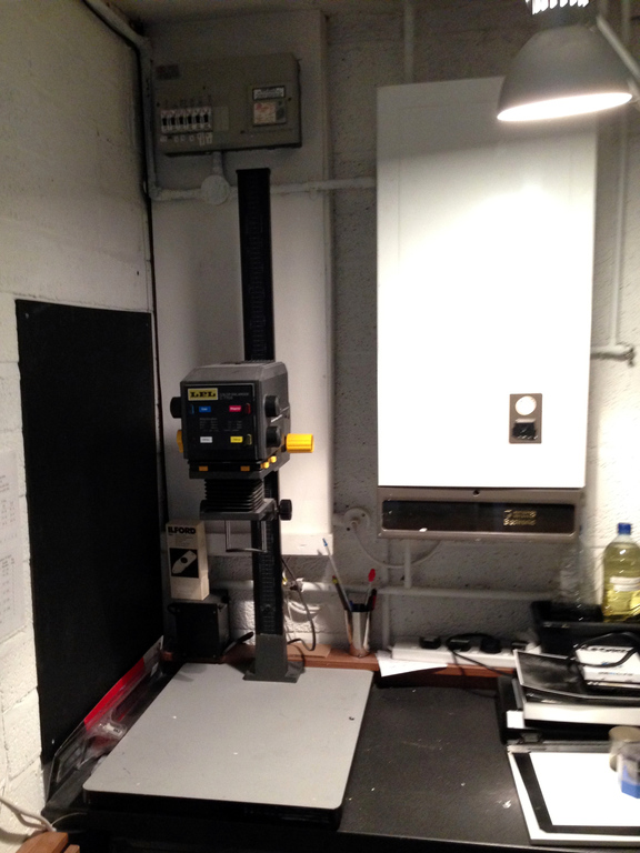
A few weeks ago I made the jump to large format photography, and upgraded my LPL C7700 medium format enlarger to a De Vere 54 large format. The C7700 is a fairly sophisticated machine from the 1970s/80s, while the 54 is a primitive beast, cast in the fires of Mordor back in 1952. It needed a little bit of modernisation to suit my needs.
The 54 came with a condenser head which worked really well with a 135mm large format lens, but was unusable with shorter focal lengths used for smaller film formats. I decided to convert the condenser head to a diffusion head. The project was a reasonable success, although I had problems with evenness of illumination. I was only able to get even illumination with such severe diffusion that I lost three stops of light, and exposure times became very long. And everyone knows I’m impatient.
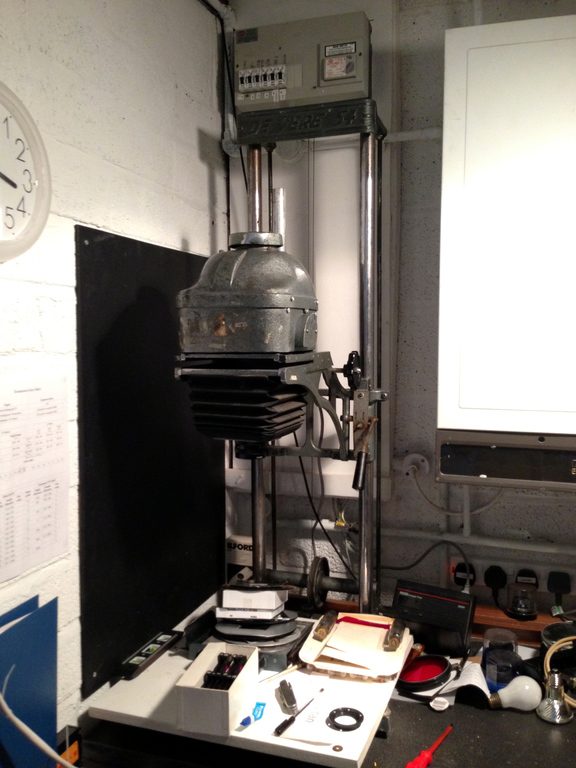
More recently, I was able lay my hands on a cold cathode head. The heads simply sit on the frame under their own gravity, so swapping is dead easy. It seems to be of original 1950s construction and still working, although the fluorescent tube seems to have developed a flicker and a loud buzz. When I opened the head up, I was shocked (not literally) by the electrical “safety” of the device. The original cabling was insulated with rubber which had long since perished and peeled away, and the wires to supply the two ends of the tube were simply wrapped around it – they could easily have come off. To make matters worse, the metal casing was not earthed. The tube itself was covered with a sheet of old cardboard, presumably not original, but marked with scorches.

I could have re-cabled the head but given that it’s basically impossible to get new tubes I decided it would be easier to convert the whole lot to run on LEDs. I read about a similar conversion project that was undertaken by someone else whose skills at electronics are far better than mine. Colour LEDs with variable contrast would have been a nice touch but beyond my ability – so I decided to keep it simple and use plain white LEDs. I’ll have to control contrast with coloured filtered instead.
The area covered by the cold cathode is about 15×18cm. Trying to keep the amount of soldering to a minimum, I investigated various LED panels including video lights such as the Yongnuo YN-300. In the end I decided to buy five Rolson work lights and remove the LED panels, each with 72 LEDs in a 3×24 grid. These are designed to run from 4×AA batteries at 6V and a fairly beefy power supply from Maplin.
With hindsight I would probably have done this differently (told you I was no good at electronics) but I wired the five LED panels in parallel, so the whole lot would run from 6V. Each of the 5 individual panels has 24 parallel branches, each with 3 LEDs in series – sharing 6V between them. Testing with batteries and an ammeter I found that the whole panel draws 1.1A. At 6V, that;s about 6.5W steady state. I have no idea if there is a current surge when the LEDs are switched on so I chose a 17W power supply that claims to provide up to 2.5A at 6V – giving me more than double the power I need.
It’s actually a multi-voltage power supply so I decided to run it at 5V rather than 6V to reduce the forward voltage on the LEDs and hopefully increase their lifetime somewhat. Under-volted at 5V they are still much brighter than the original cold cathode tube.
The power supply seems to have a capacitor across the output so when you switch on the panel you don’t get any light for 0.4 seconds. After switching the panel off, you get extra light for 0.1 seconds. This is OK, so long as I remember to compensate for the lost 0.3 seconds of light. It’s probably no worse than using a filament lamp, which takes a bit of time to reach full brightness. Over a typical 15-second exposure it’s only a 2% error anyway.
My fabrication skills are pretty bad, so I cobbled together the five LED panels with a piece of hardboard, some screws and plenty of hot glue gun.

I drilled some holes in the cast aluminium case to be able to mount the LED panel and the power supply in the top half of the casing. The original cold cathode head had contained a large ferrite transformer so it was no problem to accommodate a switch mode power supply. The head is therefore run from an external mains supply, just as the original cold cathode and incandescent heads were. This means I can still use my enlarger timer, which is a simple timing circuit with a mains relay.
The lower half of the cold cathode head contains a piece of opal diffusing plastic. It looks like it may once have been filled with water. The single diffuser on its own was not quite enough to fully mask the periodic pattern of the LEDs in a grid, so I added another piece of diffusing plastic a few centimetres above it, also mounted by drilling sideways into the aluminium casing and using machine screws. This was sufficient to disguise the slightly uneven lighting from the LEDs while still allegedly passing 95% of the light.

I also decided to modify the lens mount. This old enlarger takes lenses with a coarse 2½” thread (approx 63mm). It’s quite rare (and therefore expensive) to find lenses with this fitting, or indeed adapters to use modern M39 lenses. I have one lens in this size (an EL-Nikkor 135mm) so I didn’t want to lose the 2½” mount. I planned to add an M39 threaded flange to an aluminium panel and mount it over the original lens mount. The EL-Nikkor lens has a fairly small rear element so the 39mm mount does not obstruct it.
First I had to very carefully cut the leather bellows away from the aluminium lens standard where it had been glued for more than sixty years. I managed to do it using a credit card to get between the leather and the metal and gently ease them apart with minimal damage to the leather.
Then it was a case of drilling some holes to mount the M39 flange on the aluminium panel and the panel to the lens standard. It’s not the prettiest job ever but it works. Here’s the lens standard with the large EL-Nikkor 135mm lens and the more common sized Toshikato 75mm lens. Both types of lens can now be screwed in without using adapters.

After modifying the lens panel, I reattached the bellows using a gel-type superglue which claimed to be able to bond leather and metal. I held the leather against the aluminium by hand for 30 seconds and it seemed to stick quite well. I then contracted the bellows up as hard as I could, using the focus knob. I kept it there for a couple of hours until the glue had cured, and it seems that the bond is firm.
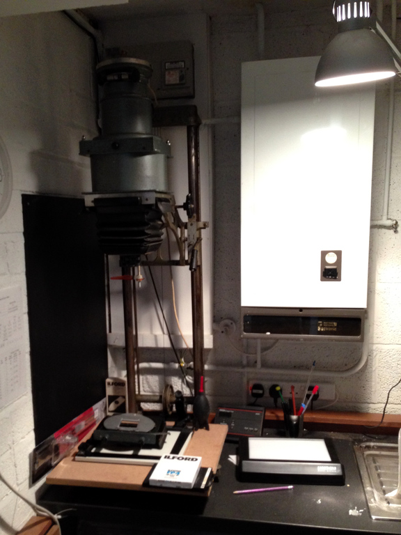
Other minor improvements were a general clean and lubrication of moving parts, and fixing the brake. The heads on the 54 is very heavy so to counteract the weight, the head is suspended from a wire which goes over a pulley at the top and is fed round a spring-loaded capstan at the bottom. To keep the head in place, it has a lever-operated brake. You can see the wire, pulleys and brake lever in the pictures at the top. I replaced the aged, cracked brake pad with new one, designed for mountain bikes.
Now I just need to find some time to get back to making prints! Thanks to my colleague Paul and my father-in-law Arthur for their help with electronics and metalwork.
